


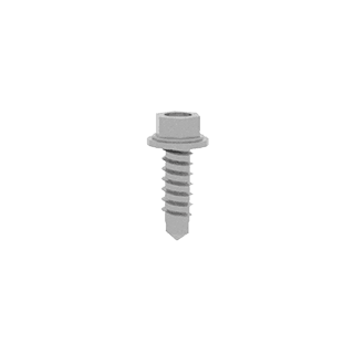

Step 1. Marking and drilling of holes
 Perform markup according to the project. Drill holes to install anchor bolts.
Step 2. Installation of SCANROC-180 consoles
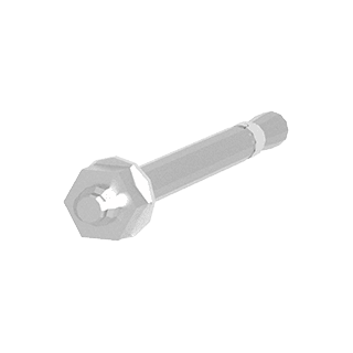
 With the help of 10×100 anchor bolts, screw the consoles to the reinforced concrete interfloor floors, pre-installing the T-3 insulation linings one pair under each console.
Step 2.1.
 Mounting point of the SCANROC K-180 console to the reinforced concrete interfloor floor. The brackets are secured with two anchor bolts for each mounting point.
After mounting the consoles, be sure to check the tightening of the nuts.
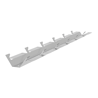
Step 3. Installation of the SCANROC P-1 sliders
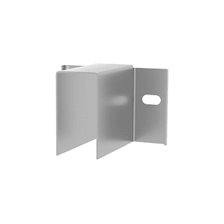
 The SCANROC P-1 slider connects the SCANROC C-100 rack and the SCANROC K-180 console. With the help of the slider, the flight length of the C-100 rack is regulated. Mounting of the slider P-1 to the console K-180 is performed with the help of hot-dip galvanized screws 6,3×19 (6 pcs for each attachment point).
Step 4. Installation of thermal insulation
 Before installing the insulation mats, it is necessary to cut through the holes through the knife for the projecting elements of the consoles. After the mats are hung, the holes in the wall (everywhere the mats) are drilled, and umbrella dowels are used to hold the mats. Technology of fastening of thermal insulation is carried out in accordance with building codes.
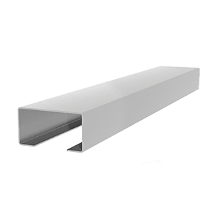
Step 5. Installation of the SCANROC C-100 rack
 The SCANROC C-100 rack transfers the load from the SCANROC decorative-protective part to the wall and attaches directly to the SCANROC P-1 slider with the help of 6.3×19 hot-dip galvanized screws (8 pieces for each attachment point).
Importantly! The heater should not touch the SCANROC C-100 rack. Maintain the required clearance according to the project.
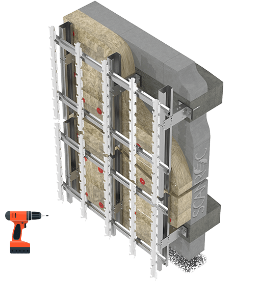
Step 5.1.
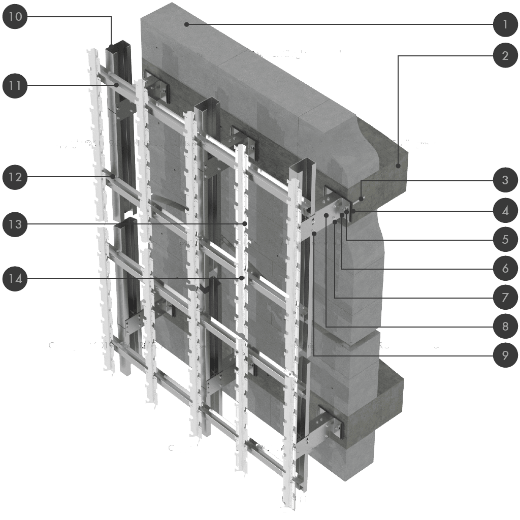
 General view of the power unit for fastening the SCANROC system to the concrete floor.
Vertical stand SCANROC C-100 is cut in factory length according to the project (inter-storey distance). This greatly speeds up the installation process and provides the required quality of the structural system.
Connection of the SCANROC C-100 racks is vertically jointed at the joints of the P-1 slider.
Step 6. Installation of crossbars SCANROC R-6
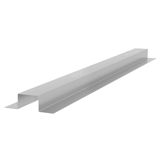
 The function of the SCANROC P-6 crossbars is to build a foundation for the placement of the vertical SCANROC C-1 racks, onto which the SCANROC facade tiles are directly hung.
Crossbars SCANROC R-6 join the racks SCANROC C-100 with the help of hot-dip galvanized screws 6,3×19 (2 pieces for each mounting point).
Step 7. Installation of SCANROC C-1 racks
 SCANROC C-1 racks function as holders of SCANROC facade tiles. The SCANROC C-1 rack is fastened directly to the SKANROC R-6 crossbar with the help of 4.8×13 hot-dip galvanized screws (1 pc for each mounting point).
Depending on the length of the facade tiles, SCANROC C-1 racks are placed in 600 mm increments (for LONG 600 × 100 and LARGE 600 × 200 tile formats) or 300 mm (for COTTAGE 300×100 tile format). SCANROC C-1.75 joints are placed depending on other formats of SCANROC clinker tiles.
Step 8. Mounting of facade tiles SCANROC
 After mounting the entire system on the protruding antennae of the SCANROC C-1 racks, the SCANROC tiles are hung.
The attachment is done by pressing on the tile and planting its groove on the antennae of the stand C-1.
Each tile should have 3 points of resistance – left, right edge and middle. At a minimum, every fifth row must be secured with additional anti-vandal antennae having SCANROC C-1 counters unless otherwise provided by the project.